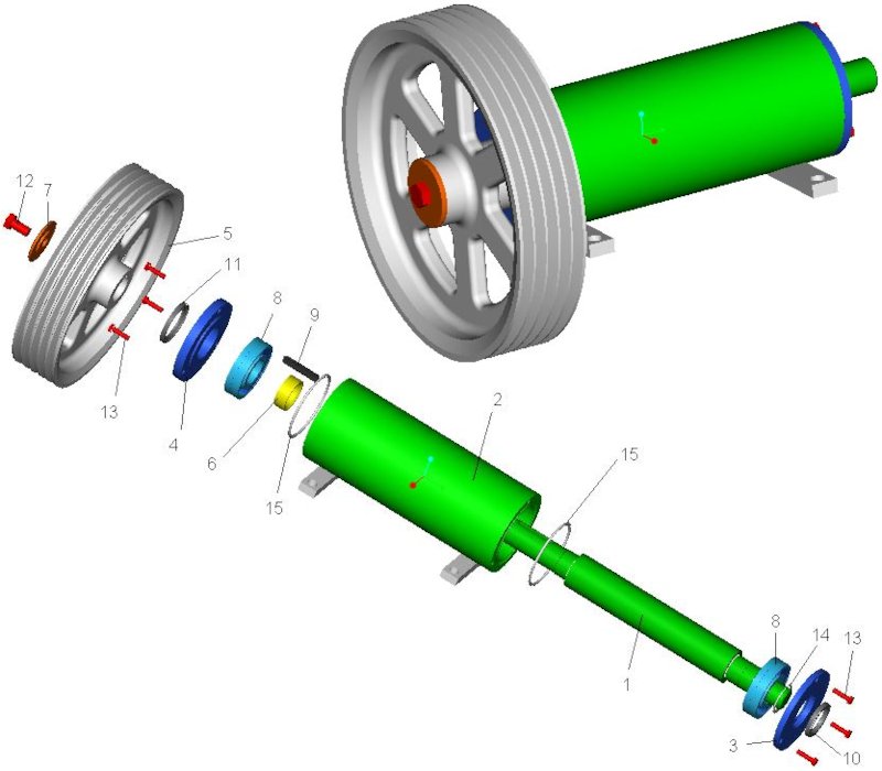
By (3D) design or CAD modelling we usually mean the creation of the design of a technical product, be it a machine, plant, equipment or structure. This enables our customer to subsequently produce the product. Subsequently, we use the 3D models, technical drawings and assembly instructions created or to be created in the product development process, as well as other necessary production documents.

Parametric CAD modeling for a structured model
CAD modeling is part of the design development process. The models are usually created parameterized. The control of models is set up in such a way that a change in the parameters has a corresponding effect on the overall model. In contrast to direct design, products are processed according to parameters rather than geometry. This allows the designer to change the model at any time. Parameter types vary from application to application. Occasionally they are process parameters (e.g. for tools) for manufacturing such as CNC offset, heat treatment or tolerance data. But also physical parameters like loads and materials, topological parameters and geometrical parameters as well as geometrical positions and dimensions are essential parts of CAD modelling. A parametrically structured 3D CAD model is ideally the database that contains the complete information about the component. Even information about manufacturing and tolerances are often included in the data set.
The internal storage of the parameter system makes it possible to find the dependencies and relationships between them. This is achieved with relationships or constraints. Data inputs from external programs such as Excel automatically link to manually entered data. These values can now use mathematical calculation methods to calculate dependencies and relationships. These constraints are usually defined as algebraic relationships, sets, logical operations, and the congruence, parallelism, and horizontality of geometric relationships.
Parameters therefore not only influence the geometric shape of a component, but they can also be defined in such a way that they are passed on via interfaces to suitable calculation software that optimizes them. The model updated with the optimum parameters, for example, in turn forms the data basis for transferring the data set to CNC production.
Advantages of intelligent CAD models
Intelligent CAD models are usually constructed in a fundamentally parametric way by applying basic design knowledge, as well as corresponding knowledge about installation spaces and geometric relationships. Therefore, the shape and geometry of an intelligent model can be controlled in the design phase by adapting appropriate values and design rules, despite little knowledge about its final shape. This is based on the so-called knowledge-based parameterization. Using size and constraint screens, 2D drawings are visible that are associated with geometry and display parameters. This is also known as dimensional geometry. To draw geometric figures, a design must be created. For example, a 2D sketch with parameterized dimensions is created in one plane, which is then extruded into the third dimension using another parameterized dimension. This results in a 3D body, which is then further developed into the final design by adding curves, chamfers, free-form surfaces or other construction elements, also using parameters.
The program attempts to identify the content and implicit symbol constraints it applies, using rule-based procedures. The user then assigns separate sizes to the finished part geometries until they are fully parameterized and assigned to the associated assemblies in the overall design.
Structured procedure for CAD model creation
Engineers therefore attach importance to a parametric model structure with gradual geometric shapes for good reasons. For this purpose, the designer creates primitive parametric 3D bodies and processes them accordingly. Alternatively, he creates 2D sketches, which he then extrudes into more complex 3D bodies. These primitive bodies (cylinders, cuboids, etc.) or extruded 2D sketches are then supplemented with 3D elements (curves, chamfers, holes, etc.). The proportions and limits of the development engineer can of course be adjusted to a certain extent according to personal intentions. However, a parametric design of the model structure ensures that several development engineers can work on several adjacent assemblies at the same time, while basic dimensions and relationships of the components of a model to each other remain unchanged.
However, CAD modelling should always be carried out in successive stages, as the individual steps complement each other. A prerequisite for the correct creation of the structure is careful planning. For this, designers need a cool head and a good understanding of their own organization and planning. CAD modelling is ideal for all product designs.
Computer-aided design procedures simplify the work and save time and costs for your company !
Find out how we can support you as a CAD service provider in the modelling and structuring of your CAD models!
Are you curious ?
Inform yourself about our complete range of services and contact us !