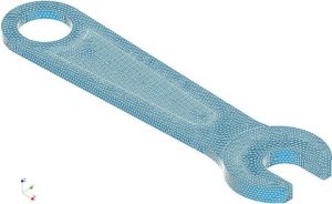
The Finite Element Method Definition, or the FE- Method for short, is a computational technique used to solve certain physical problems approximately. It enables the prediction of complex stress conditions in technical components, which inevitably arise due to the action of forces, pressure or temperature.
In this method, the entire component geometry is subdivided into smaller elements that are nevertheless mathematically relevant due to their size (finite as opposed to infinite - infinitely small). This subdivision results in the mesh characteristic of the FE method.

This representation of the component and the boundary conditions to be simulated then represent a system of differential equations that can be calculated with the help of numerous iterations and represent an approximate solution to the input problem.
This procedure is particularly important for determining the strength and deformation of the materials used under real conditions. It helps to verify the stresses acting on the component geometry and to determine whether component failure (e.g. deformation or fracture) will occur. Accordingly, FEM as a simulation method plays an important role in the prevention of real damage cases, which could otherwise have tragic consequences.
Application examples
The finite element method is used, for example, for engine components, since a large number of mechanical, hydraulic and thermal loads interact in the engine. The method is also used on a larger scale, for example, to determine the accident characteristics of car bodies as part of a crash simulation. In practice, the FEM method is used to investigate thermal problems, magnetic fields and loads on components. In the meantime, it has found its way into all industries. Thus, FE analyses are carried out from the smallest plastic component to heavy mechanical engineering.
How is an FEM simulation carried out in detail?
The finite element simulation starts with a 3D model of the component, which is created with CAD software. Subsequently, a so-called meshing algorithm divides the surface of the model into smaller units that represent the geometry of the surface in detail. The nodes of this mesh now represent the initial state of the component. The mechanical parameters of all materials used, such as yield strength, modulus of elasticity, etc., and the acting forces of the loading situation form the basis for the subsequent calculation. All restraints of the component are also essential. The differential equations resulting from these boundary conditions are then solved with a so-called solver. This solution process proceeds iteratively and converges at some point to an almost optimal solution.
Finally, the last step is the analysis of the results. For example, it is shown graphically and in colour how large the displacement of the individual nodes of the initial mesh is after the load has been applied at different points of the component and what this means for the total load. In this way, we can reliably determine loads that would possibly result in a fracture.
On our pages you will learn how you can accelerate and optimize your product development process with the help of the Finite Element Method.
Are you curious ?
Inform yourself about our complete range of services and contact us !